Nintendo 64 was released in Japan and USA in 1996 and Europe and Australia in 1997. It was the successor the Super Nintendo and introduced 3D graphics similar to other popular consoles at the time, such as SEGA Saturn and Sony Playstation. The reception of the console was generally good, and the transition from 2D Mario to 3D Mario in Super Mario 64 was deemed successful. A few critics, including us, dislike the gamepad, especially the analog stick, which was prone to failure over time.
As with any console, the Nintendo 64 requires service over time due to wear and tear, and aging electronic components. In this post we will show you how to disassemble the N64 and replace the capacitors. While the capacitors of the N64 is not prone to failure, they are aging and _will_ fail eventually. I was a bit worries when the image of my Nintendo 64 was washed out and blurry, but this was an issue with 3rd party AV-cables and PAL-consoles rather than a hardware issue (so, if you own a PAL console, make sure to stick with original AV-cables).
Step 1: Disassemble the Nintendo 64
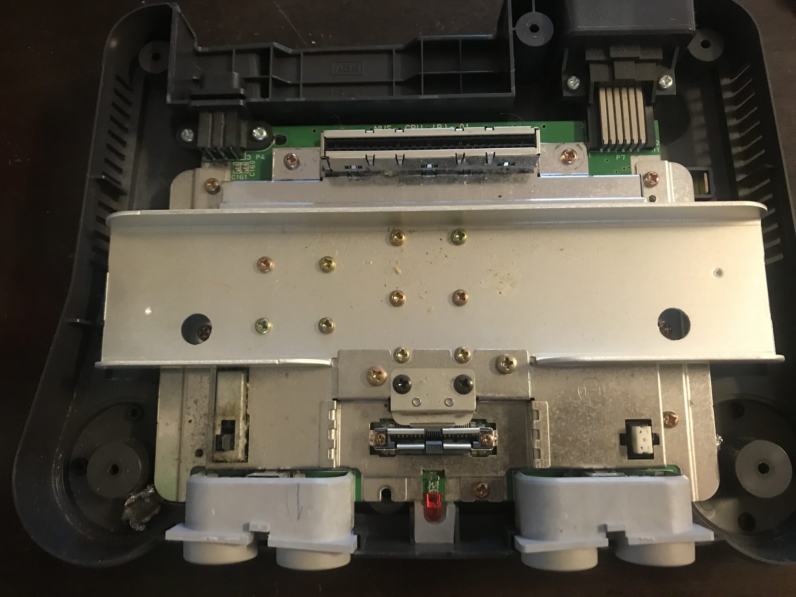
To open the N64, grab a gamebit screwdriver and remove the six screws from the underside of the console. This will reveal the cooling unit and shielding on the mainboard as seen in the images below. Remove all the Philips screws to detach the mainboard.

Step 2: Recap
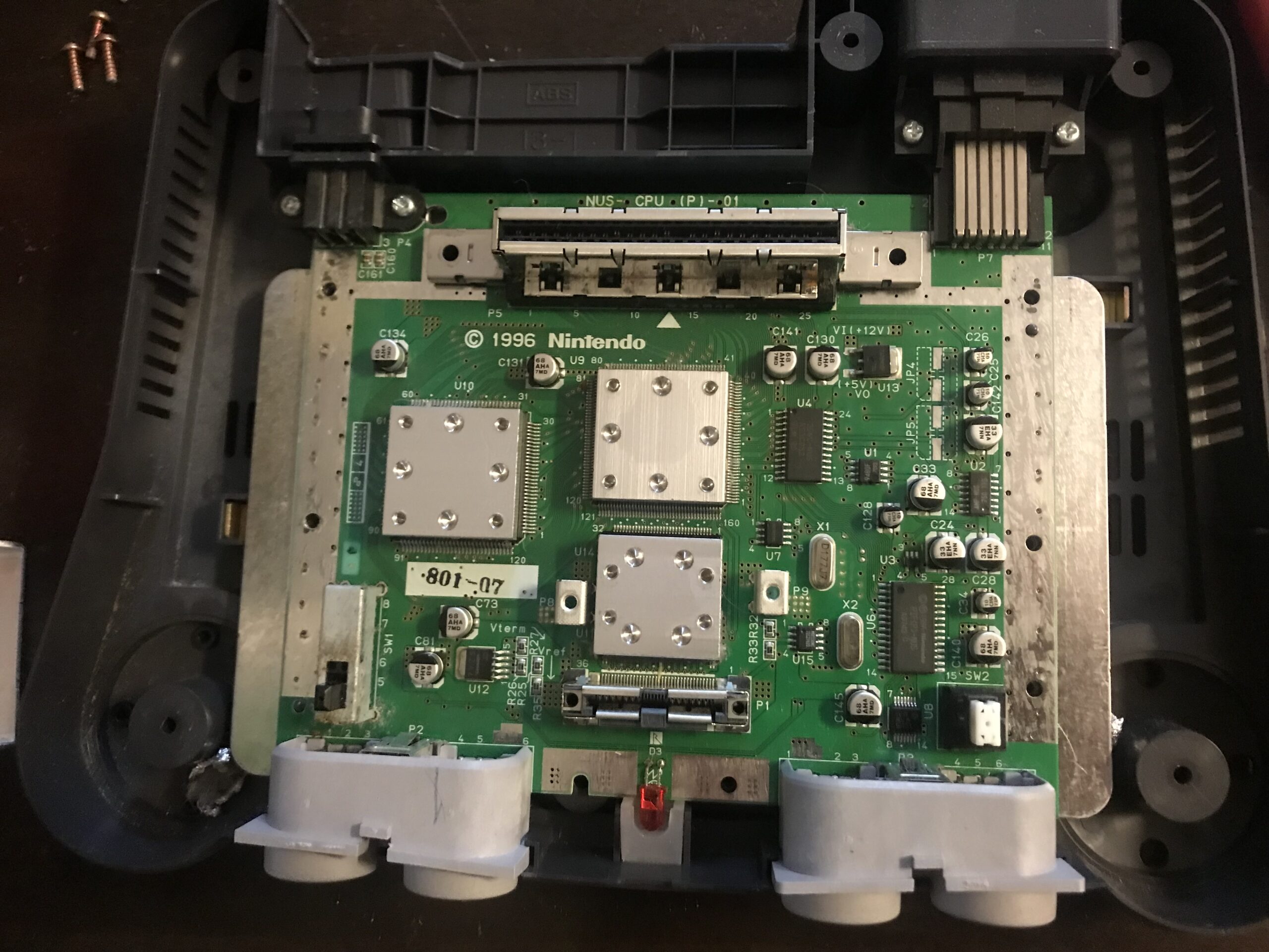
As seen, the capacitors on the Nintendo 64 are surface mounted SMD:s. To check with capacitors you need, go to https://console5.com/wiki/N64 and find the model of you unit’s mainboard in the list. This information can be found under the C 1996 Nintendo text on the mainboard.
My unit has a NUS-CPU(P)-01 PAL mainboard in it, and I thus need the following capacitors:
C24 33uF 25v
C25 10uF 16v
C26 10uF 16v
C28 33uF 25v
C33 68uF 10v
C34 10uF 16v
C73 68uF 10v
C81 68uF 10v
C128 10uF 16v
C130 68uF 10v
C131 68uF 10v
C134 68uF 10v
C140 68uF 10v
C141 68uF 10v
C142 33uF 25v
C145 68uF 10v
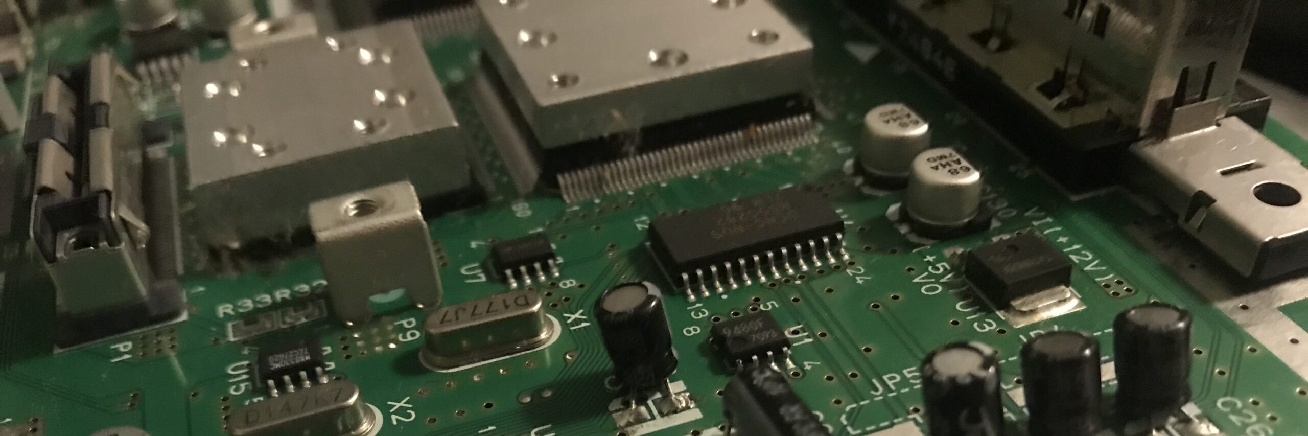
These can be easily found on the mainboard, as each capacitor is labeled. The black half circle on the capacitors is the negative pole. They are fairly easy to remove: add some flux, and heat one side of the pad with your soldering iron, carefully wiggling the capacitors. Repeat for the other leg. Eventually it will come off. Clean the pads and add some extra solder to them before you solder a new capacitor in place. Make sure your replacement capacitors are not too big so they get in the way when you assembly the unit again. In some cases, you need to place them in an angle so they do not touch the heat sink, so leave a little wiggle room by not cutting the legs of the capacitors to short.
While you have the unit open, it is a good idea to clean all the surfaces: use alcohol for the electronics, and soap and water for the plastics. Give special attention to the cartridge and jumper pak ports. Also, check for cracked solder joint and reflow them as needed. I gave the joints surrounding the AV-port a go with the soldering iron.
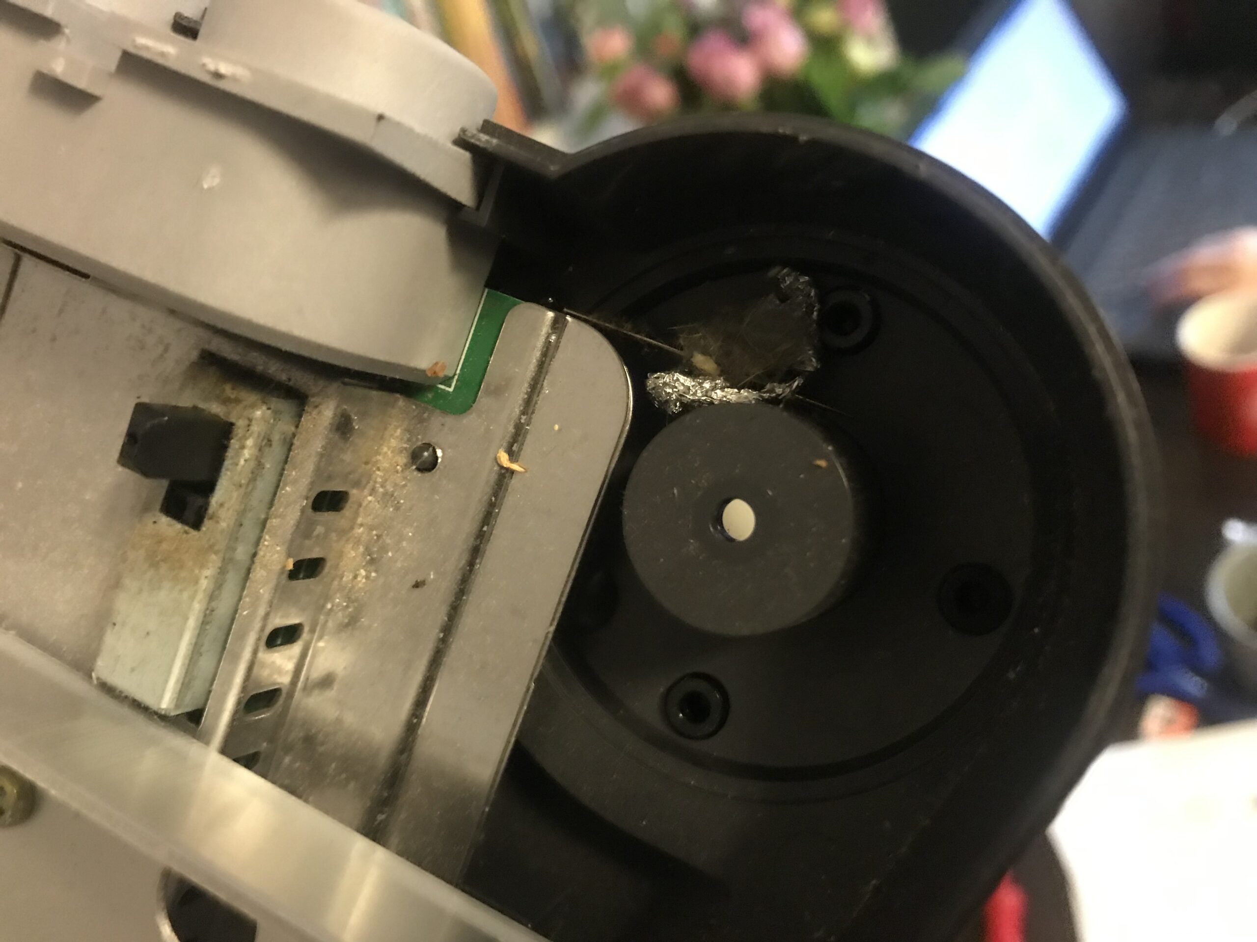
As seen below, my Nintendo 64 was filled with dirt, and I found parts of toys, aluminium foil and a sewing needle(!) inside my unit.
Hello, I found myself on the NUS-CPU (P)-01 motherboard, with the SMD ceramic capacitor called “C45” on the back that is missing because it came off… could someone help me understand how many Uf and how many volts it could have, because I can’t find any information. Thanks for understanding.